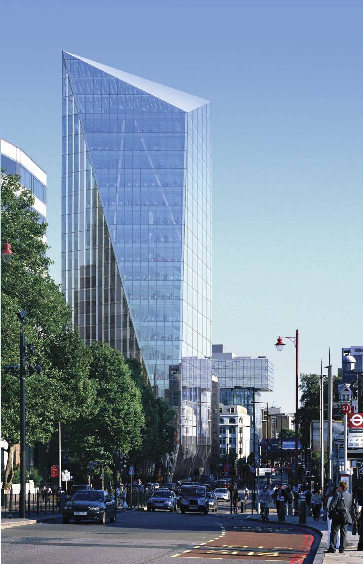
- Client: Great Portland Estates
- Lead Contractor: Mace
- BIM Tools: Autodesk Navisworks; Dome Connect
The design development for the chiseled office tower at 240 Blackfriars was unusual, in that the speculative office scheme originally had planning permission for just 13 storeys. But following a post-crash rethink, developer Great Portland Estates decided to add an additional five storeys and aim for a higher BREEAM rating to attract tenants, placing greater demands on the environmental performance and M&E plant.
To help both with offsetting the cost of achieving higher energy performance and to coordinate the enhanced MEP design, the client decided to embrace BIM.
Mace tendered for the project in mid-2011. In other words, this was after the Cabinet Office had thrown down the BIM gauntlet in the Government Construction Strategy, but before PAS 1192:2 defined the BIM roles of clients, designers and contractors.
At the time, says David Hammond, Mace’s head of design and engineering, both Mace and Great Portland Estates were “struggling” with what BIM really meant, subliminally equating it with 3D design models rather than data collection and management. “But here the question was how can we derisk the coordination and construction of a complex building,” Hammond says.
The basement structure was procured separately by GPE, allowing the developer to proceed quickly with the main contract when it judged the market conditions were right. But this meant Mace had to verify and adopt the structure, a process that Hammond says was simplified by the use of laser scanning (by specialist SES).
“We took the laser scan survey and placed it over the initial prototype so we could see whether the design intent model matched the as-built conditions. It roved to be accurate, economical and authoritative.” Hammond notes that Mace uses the process “regularly” now, but it was relatively unusual in 2011/12.

240 Blackfriars: positive BIM experience
The challenge was assembling a plant room in a complex structure 100m off the ground so we had a 3D model that we used to rehearse the build process with the design and construction teams and subcontractors. It went in place very smoothly – which moves, which order, which plant and steel went in in which order.– David Hammond, Mace
As the project had previously reached pre-construction in 2008, architect AHMM had already created an advanced package of 2D information. Conversion and reworking of all the existing data would have been expensive so the translation of 2D info into BIM was outsourced to a 3rd party.
BIM specialist BIM Technologies was employed – first by GPE, but then nominated to Mace – to convert the 2D information into a 3D design model, then integrate it with structural and MEP models from structural engineer AKTII and services consultant Hilson Moran. The models were brought together using Autodesk Navisworks, and the resulting “federated” model was then used in all design team meetings and for design coordination.
Derisking the project was a key driver for using BIM, and the principal arena for this was the building’s three-storey rooftop plant area. As Hammond explains: “The challenge was assembling a plant room in a complex structure 100m off the ground so we had a 3D model that we used to rehearse the build process with the design and construction teams and subcontractors. It went in place very smoothly – which moves, which order, which plant and steel went in in which order.”
Overall, BIM meant that GPE was able to reduce the 5% of the budget set aside for MEP installation and fixes to 2.5%, so using BIM in effect recouped its own costs. But those are the hard savings, and Hammond chalks up several “soft” factors. “We had greater enthusiasm from the designers, better collaboration, and better prediction of issues in terms of coordination – all the things you’d expect.”
Mace then decided to take the next step of creating additional models of the fabrication drawings from MEP and other subcontractors. “The supply chain was wary about it, but we helped them with the process, expectations and the model format,” says Hammond. “So we’ve produced an as-built model that’s now been adopted by GPE, although that was not really the intent to begin with.”
It’s tempting to imagine that the as-built model incorporates the accumulated data from every stage in the design and construction process, but Hammond points out this is a misconception. “Eventually, the design model ‘falls away’. AKTII’s original model, for instance, is adapted by the steelwork contractor’s model, which is based on the detailed fabrication designs. So the as-built model is derived from the subcontractor’s model, not the consultant’s.”
Mace and BIM Technologies are currently producing an Operation & Maintenance (O&M) manual, produced in the Dome Connect system, a software platform often used to capture information from as-built drawings in order to create an online “handover manual”. Although COBie UK 2012 had been released when the 240 Blackfriars team was making decisions about data gathering, they decided that it was not yet mature enough and used an alternative scheme for asset identification.
However, Hammond concedes that it has proved harder than expected to link Dome Connect to the databases held in Autodesk Navisworks.
But Mace has undoubtedly had a positive experience of BIM that it wants to share with the rest of the industry. “We’re very open with the rest of the industry, we’re an active member of the Open BIM network, so we’ve made a decision to be collaborative. The government strategy is about upskilling the industry, so we want to be participative about that,” Hammond concludes.


